Camshaft quenching complete equipment serves as a core component in internal combustion engine manufacturing. It is specifically designed for the induction quenching of camshaft cam tips (cam profiles) and journals, aiming to enhance their wear resistance, fatigue strength, and resistance to pitting corrosion. The following sections detail the equipment’s composition, technical characteristics, and selection guidelines:
I. Core Components of the Equipment
Module
Function Description
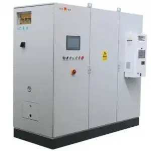
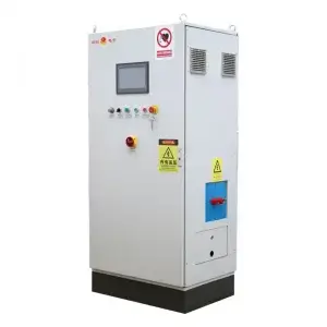
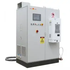
Induction Heating Power Supply
Ultra-audio frequency/medium frequency power supply (IGBT or MOSFET), with a power range of 50–300 kW and a frequency of 10–100 kHz, suitable for precise heating of complex camshaft profiles.
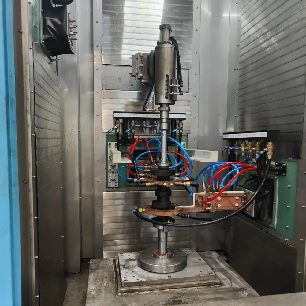
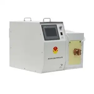
Quenching Machine Tool
Multi-axis CNC machine tool integrated with camshaft rotation drive (10–200 rpm), sensor profile-moving (XYZ three-axis ±0.05 mm accuracy), and quenching medium spraying system.
Cooling System
Closed double-circulation cooling (internal circulation: water cooling for the power supply and coils; external circulation: constant temperature control for the quenching fluid), with a flow rate ≥30 L/min and pressure of 0.2–0.5 MPa.
Intelligent Control System
Controlled by CNC or PLC+HMI, supporting multi-cam segment programming, temperature closed-loop feedback (infrared temperature measurement), and process data traceability (compatible with MES integration).
Detection Module
Online eddy current hardness detection (±1 HRC accuracy), laser profilometer (cam tip shape error ≤0.02 mm), and metallographic sampling system.
II. Technical Characteristics and Advantages
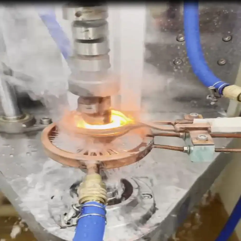
Precise Quenching for Complex Profiles
Profile-Matching Sensor Design: Customized multi-turn coils are engineered according to the shape of cam tips (tangent lines, arcs, functional curves) to ensure that the hardened layer (1–5 mm) matches the profile and the hardness gradient remains gentle (HRC 50–60).
Multi-Axis Linkage Control: The sensor moves in sync with cam rotation, dynamically adjusting the heating position (accuracy ±0.1 mm) to avoid overburning or under-quenching at the root or tip of the cam.
Efficient and Flexible Production
Segmented Scanning Quenching: Each cam and journal on a single camshaft is processed sequentially, supporting independent programming of different cam parameters (lift, base circle radius) with a model changeover time ≤10 minutes.
Production Cycle: The total processing time for a four-cylinder camshaft (8 cams) is ≤3 minutes, with a daily production capacity of 300–500 pieces (depending on shaft length and the number of cams).
Intelligence and Consistency
Temperature-Power Closed-Loop Control: Infrared thermometers monitor the surface temperature of cam tips in real time (±5°C), dynamically adjusting power and movement speed to ensure stable austenitization temperature (850–920°C).
Energy Efficiency and Reliability
Energy Recovery System: Waste heat from the quenching fluid is reused to preheat cold water or workshop air conditioning, reducing energy consumption by 20–30% (compared to traditional furnace quenching).
Redundant Design: Dual power modules and standby cooling pump sets ensure an MTBF (Mean Time Between Failures) ≥10,000 hours.